|
Maintenance and Issues
|
Maintenance |
Issues |
|
Information on setup and use of JP Diag
and IAW Diag ECU diagnostic Software
ECU Installed in 2002 ST4s: Magneti
Marelli IAW 59M
The TPS is PF09
IAWDIAG ECU Diagnostics Software and
ECU Reader and Writer
Info
and How to for Superseal 1.5mm AMP connector pin removal and assembly
2002 Ducati ST4s Manuals: Work Shop
Manual (large file +35Mb but text searchable)
Electrical Schematic
Parts Manual
Owners Manual
(IT, EN, FR, DE)
Ducati ST FAQ (Perry
Rosenboom - Archive Copy v1.4) |
Handy Capacity Values for ST4s:
| |
|
|
|
Oil Quantity |
3.7L |
~
3.9qts |
|
Coolant Quantity |
3.5L |
~
3.7qts |
|
Fuel Quantity |
21L |
~
5.5gal |
Front and Rear Wheel Torque Values
| |
Ft-Lbs |
N-ms |
| Front Axel nut
-- 28mm socket for nut |
46 |
62 |
| Front Axel Pinch
bolts -- 12 mm head |
14 |
19 |
| Front Brake Caliper retaining screw |
30 |
43 |
| Rear Axel nut
-- 30mm head |
61 |
83 |
| Rear Chain Adjust
bolts -- 12mm head |
5.9 |
8 |
| Front Sprocket Plate
bolts -- 8mm head |
4.4 |
6 |
Oil Change Related Torque Values:
| |
Ft-Lbs |
N-ms |
| Oil Filter
Cartridge |
8 |
11 |
| Oil Drain Plug |
30 |
42 |
| Oil
Mesh Screen |
30 |
42 |
| Oil
Mesh Screen outer Cap |
30 |
42 |
Engine Mount Bolts Torque Values
| |
Ft-Lbs |
N-ms |
| Rear engine mount bolt -- 12mm
bolt thread
(14mm bolt head, 15mm nut) |
45 |
60 |
Link to Other Torque Values
|
1. Battery
would not maintain a charge
2. Brake
reservoir cap corroded
3. Lower
steering head bearings corroded and seized
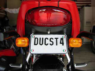
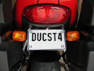
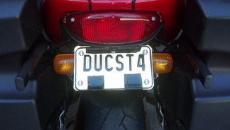
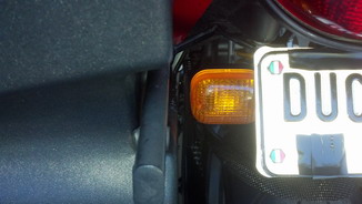
4.
Installation of Evoluzione license plate re-locator
5. LCD
display module partial failure and repair
6. Relay failure
7. High coolant/water temperature under normal running conditions
8. Output
shaft wear and front sprocket retention plate wear
9. Radiator
Pressure Cap part number incorrect in the Ducati Parts Catalogue.
Correct PN is:89310031A
10. Brake Shudder
/ Judder / Chatter
11. Neutral Switch
Failed 12. Tensioner and Idler Pulley Bearing (timing Belt)
Replacement: Tensioner and idler bearings are not the same!!!
Idler Bearing PN is: SKF 6003-2RS1/C3GJN (GJN is grease spec, high temp)
Tensioner Bearing PN is: SKF 61904-2RS1
|
|
Events and
Receipts
1. 600 mi First service
2. 3,000 mi oil change
3. 6,000 mi service
4. 9,000 mi oil change
5. 12,000 mi service
6. 15,000 mi service
7. 16,400 mi service
8. 18,500 mi service
9,
24,000 mi service
10. 30,000 mi service |
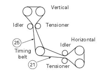
Install and Set Timing Belt Tension Values using acoustic
vibration:
Measure and set Tension on timing belts: 110Hz on new Ducati OEM belts and
approx 90-100Hz on existing belts. Set tension at 100Hz for New Exact Fit
belts (CA Cycleworks).
To set the belt tension, the cylinder you are checking MUST be at TDC so
that there is no tension applied to the belts by the closing springs pushing
on the rockers.
1. For the horizontal cylinder it is the forward run between the
tensioner pulley and the exhaust camwheel (posn 21).
2. For the vertical cylinder it is the rearmost run between the
idler pulley and the exhaust camwheel (posn 25).
|
Suspension Info
Fork Overhaul and Oil
Replacement - Ducati ST4s Showa Forks ('02-'03 Ducati ST4s)
Fork Overhaul and Oil
Replacement - Ducati ST4s Showa Forks ('02-'03 Ducati ST4s) - pdf
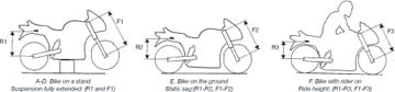
Preload (24 Dec 20)
| |
|
Front |
Rear |
| 1-2 |
Static Sag |
|
|
| 1-3 |
Rider Sag |
|
|
Ohlins recommendations:
| |
|
Front |
Rear |
| 1-2 |
Static Sag |
15-30 |
10-20 |
| 1-3 |
With Rider |
35-50 |
25-40 |
*measurements in mm.
|
25 December 2020 |
Front |
Rear |
| Compression Damping |
|
|
| Rebound Damping |
|
|
Tire Pressures: Front- 33PSI; Rear- 35PSI
|
|
IAW DIAG Setting Trimmer Value IAW5xM ECU has two types of memory:
Flash-Memory, where the bin-file (aka fuel map) is stored and EEPROM -
electrically erasable programmable read-only memory, where data like Serial
number of ECU, TPS-Valence-Trim-Value and is stored
When you flash your ECU, it does not change the EEPROM (you may see the
eeprom-tool from the guzzidiag-page) therefore, it is not necessary to
complete a TPS Reset if you reflash an existing ECU in your bike (No change
to the TPS-Valence-Trim-Value stored in EEPROM)
It is not harmful, but it is not necessary. Only changing the Hardware
(ECU or TPS) makes it necessary to do a TPS Reset, or a worn TPS.
For the CO-Trimmer Setting:
The 5AM ECU operates stock in Closed Loop Mode, and the CO is controlled by
Lambda sensors. The Value of the CO-Trimmer is set to zero from factory,
you can’t even change this value as long Lambda sensors are active.
If you reflash the ECU with a map "Lambda off" -- as described above the
Trimmer-Value remains at Zero.
The bike will run, even with no change to the CO-Trimmer. It
will run much better in the Low/mid-rpm range, if CO is set to around 4.0 -
4.5% as measured with a gas-tester. If no gas-tester, set the CO
Trimmer to a value of around 24.
According to those with experience, CO level of 4.0 - 4.5% equates
to a trimmer value between 22 and 28. |
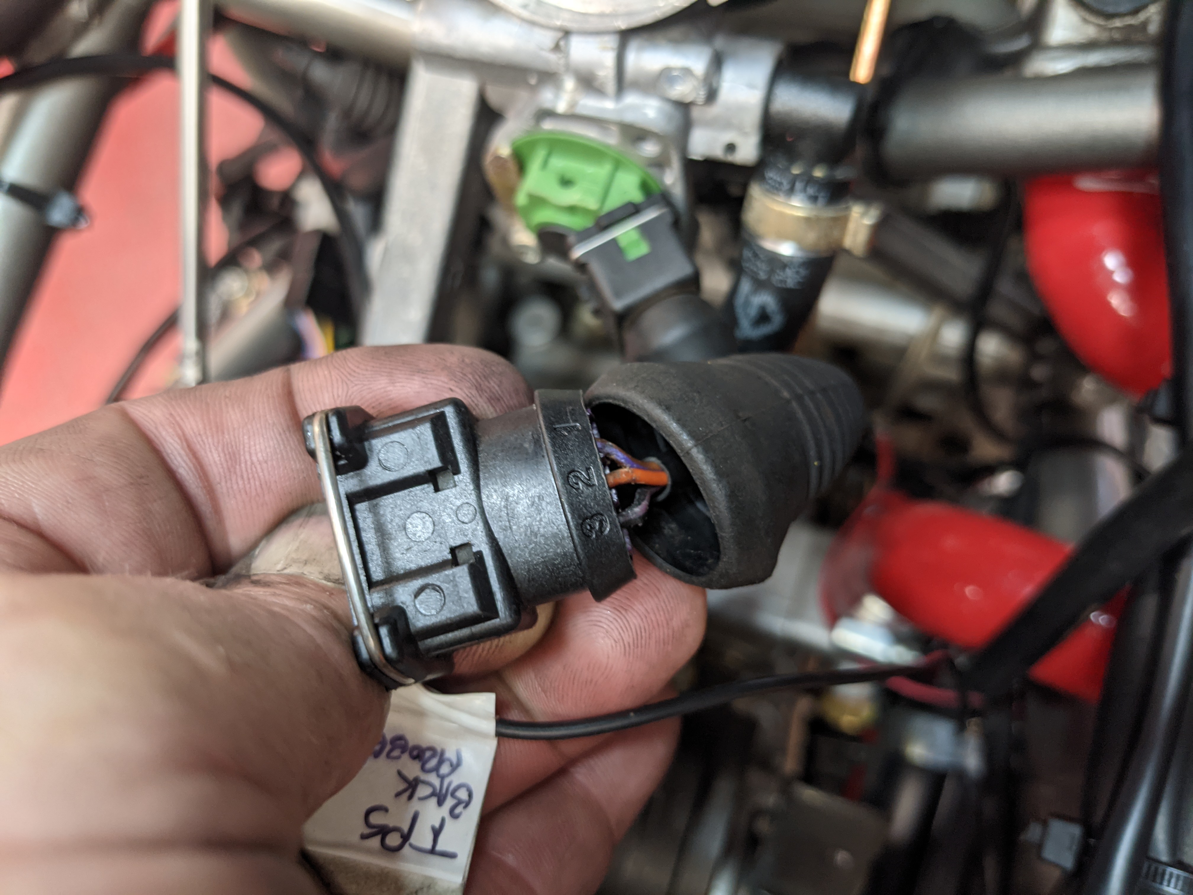
ST4s Non Linear TPS - Set Baseline Adjustment
Brad The Bike Boy has a
comprehensive page dedicated to this with the
CAUTION: Do NOT connect Diagnostic
SW and press "TPS RESET" - NO!
Do NOT do it if you have Non
Linear TPS (like my 2002 ST4s does)
http://www.bikeboy.org/ducati4vthrottleb.html
pdf printed version of Brad The Bike Boy's TPS instructions
Vinnie's info on TPS Reset
Follow Brad the Bike Boy's
instructions. I
back probe the TPS at the connector, red lead (+) from my multi-meter to the
#2 wire (orange) in the middle of the connector, and my black lead (-) to
the #3 wire (black & violet).
 |
|
Other ST4s Issues/Troubleshooting Info 1.
ST4s wouldn't rev above
4k
(https://www.ducati.ms/forums/40-sport-touring/44833-st4s-wouldn-t-rev-above-4k.html) |
|
|
Issues
Replaced the Battery and Cables and added Headlight Gizmo
(see the Mods page)
[TOP]
 |
2nd Issue... paint
peeling and corrosion of the brake reservoir cap |
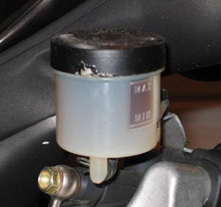
Noticed paint peeling and corrosion of the (aluminum?) cap.
I don't park it on the side stand and there is no trace of brake fluid leaking. L 21 Months after purchase... wonder if it is
covered by warranty? Well So far, no word on warranty. Ducati
Nashville did order and replace the cap. $25 for a new one. The
original problem was the rubber seal in the cap had developed a leak (pin hole)
and the fluid caused the cap paint to peel and corrode. There was a small
amount of brake fluid between the seal and the cap that caused the problem.
[TOP]
|
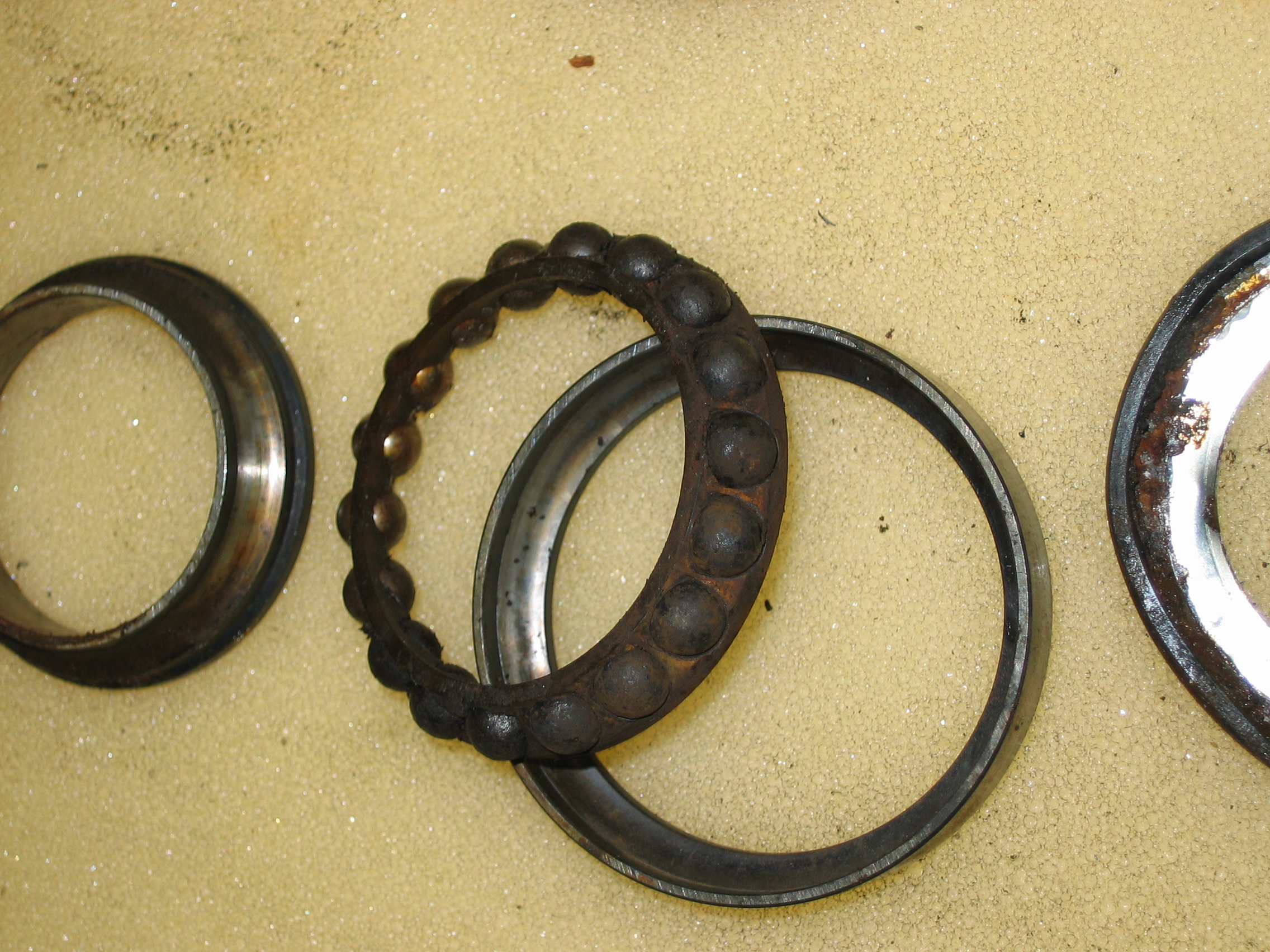
3rd Issue... Lower Steering Head bearings corroded and
seized: |
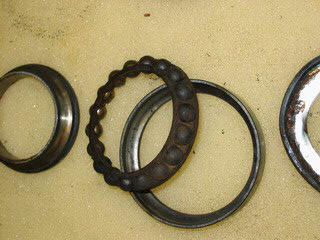
This issue was first
called to my attention by Ian of www.st4s.com.
He pointed out that several ST4s owners had a similar problem and encourage
current ST4s owners to have it checked, especially while under warranty.
Very sound advice. I had mine looked at during the 6,000 mi service and
look how bad the bearings were. Click on the photo for a more detailed
picture, or click here for a
very high resolution photo.
[TOP]
FIX!!!
[TOP]
|
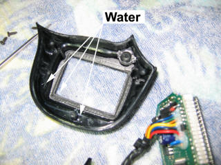
5th Issue... LCD Module display (LCD Panel)
partial failure. About a month after a very rainy and wet ride, my LCD
display started to fail. It would only display the top half and lower
right portion of the display, I could see temperature and time, but only
half my tank of gas. This seems to be a common problem or so I have
read on some of the forums. I spent the time on a cold Sunday
afternoon and removed the LCD module and set about repairing it. This
is how I did it: |
Click on any of the photos for higher resolution image
1. Remove the upper
fairing to get at the instrument mounting plate.
2. Disconnect the
speedometer (odometer) cable.
3. Remove the bolts
attaching the instrument mounting plate.
4. Detach the instrument
cluster from the mounting plate.
5. Remove the single cap
nut from the back of the LCD module and disconnect the two pig-tail electrical
connectors. (the connectors will pass through the back of the housing one
at a time with care.
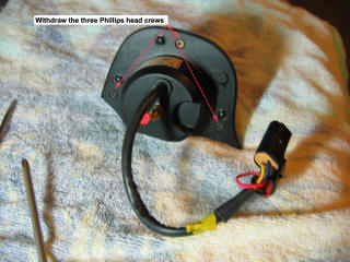
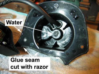
6. I placed the
LCD module on a towel and removed the three small Phillips head screws.
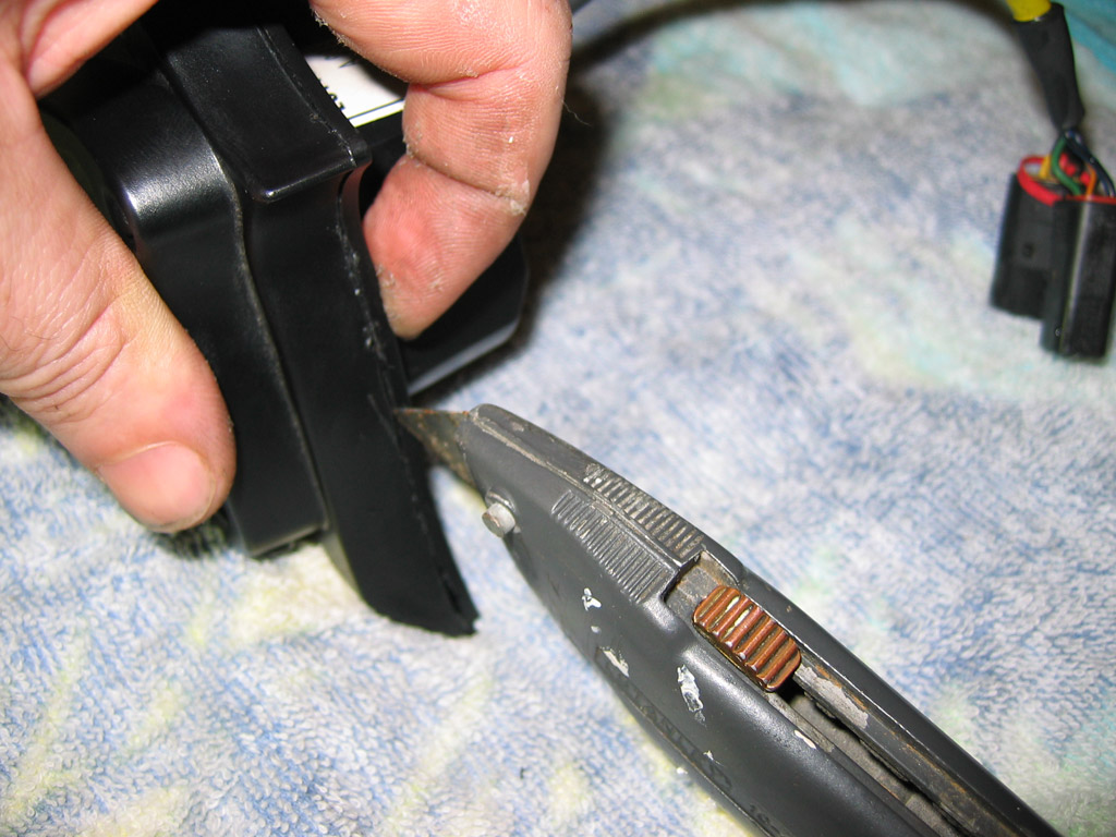
7. Using a sharp sturdy
blade, drew along seam at the bottom of the module until cutting the glue bond,
then using a small flat tip screwdriver worked the plastic halves apart by
slowly and gently first the bottom half then the rest of the module.
(you can see I accidentally scored a bit of the plastic)

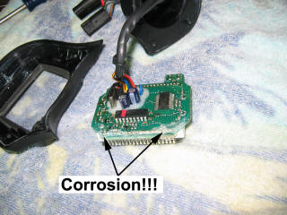
8. Once halves of cover are apart,
remove the LCD display and circuit card assembly. My LCD module had a
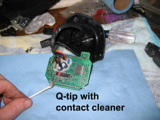
considerable amount of water in it and corrosion on the circuit card. Used
a Q-tip with a little contact cleaner to remove the corrosion, then used a
dry Q-tip to remove any residue.
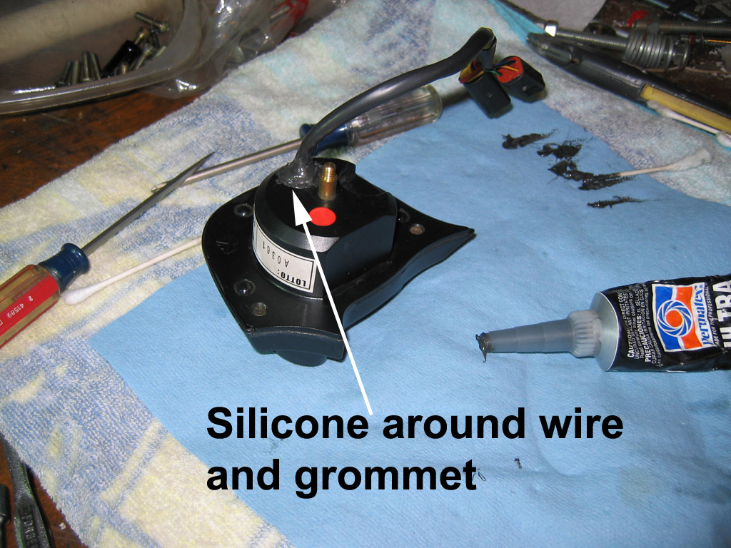
9. When I put it
together, I used black silicon RTV all around the edges of the two halves and
the three screw holes. I also used RTV around the grommet where the
electrical pigtail passes, I think that is the culprit that allowed the
water into the LCD module in the first place.

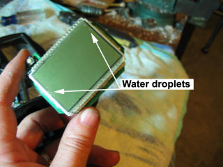
10. Update: After
12 years, the trip computer LCD display started to fail again. Much more
significant than the first time, loosing portions of temperature display, fuel
bars, etc. I attempted to clean corrosion again but this time to no avail.
I did notice that water intrusion seems to be occurring through the time set
button. I did have some significant weather during the May 2021 ride at ECM and
it sat through a big storm while parked at Fontana Dam Resort and even though
the bike has been dry since, and garage kept, the display failed and still has
some water inside. I opened it up and saw a few little droplets sticking near
the time adjust button.
I purchased a replacement via eBay. I did place preemptive RTV around the back
grommet where the electrical pigtail passes of the new display. I am thinking
through some additional protection around the time adjust button but do not want
to have it prevent the use of the button. Tiny little clear silicon around the
circumference of the button perhaps, but do not want the button to stick.
[TOP]
|
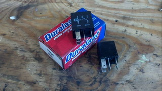
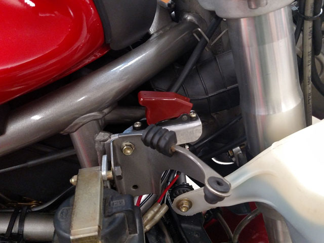
6th Issue... Relay
failure of primary relay located next to fuse panel under left side instrument
trim. Replaced with Duralast Relay PN# 19283 |
other relays that can be used are: preferred: Siemens V23073 & V23074 and
Tyco A1001-A402 & A1001-A403
or:
Bitron B047E 46520411-232006 & 232008
Borg-Warner (BWD) R3223
BMW 61 36 1 393 412 & 61 36 1 393 415
Bosch 0-332-207-307
Ducati 541.4.003.1A & 541.4.010.1A
Ford F57B-14B192-AA
Hella 4RD 931 524-02
Hongfa HFV6 012ZS-TR & 012HS-TR
NAIS ACM13221 & ACM33221
NHG NVFMCZ20 & NVFMCZ25
Omron G8HN-1A2T & G8HN-1C2T
Siemens V23073 & V23074
Song Chuan 871-1C-S-R1-12VDC
Tyco A1001-A402 & A1001-A403
Zettler AZ988-1CT-12DC1R(201)
[TOP]
|
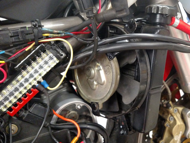
7th Issue...
High coolant/water temperature under normal running
conditions. Drained and flushed cooling system (used Liqui-Moly
cooling system flush) rinsed and refilled with Engine Ice. Temperature
sensors replaced, and replaced radiator pressure cap. ** Note the part
number for the pressure cap is incorrectly shown in the Ducati Parts
Catalog. Got it straightened out with Ducati North America by working
with Ducati, Omaha...they are super. Checked the water pump impeller,
all looking good; refitted water pump housing. Straightened radiator
cooling fins. Second Cooling Fan Installed
- Right Side, manual switch controls both fans. |
[TOP]
|
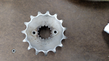
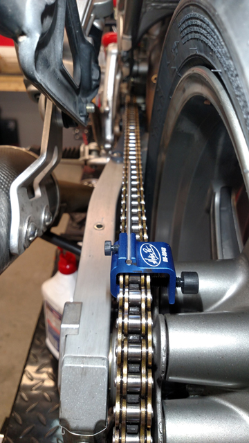
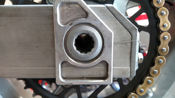
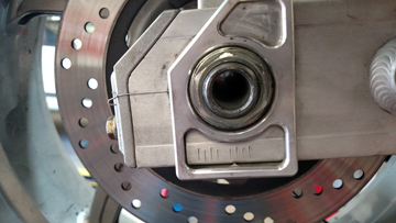
8th Issue...
Output Shaft wear in the channel caused by front sprocket retention plate, due
to misaligned chain! |
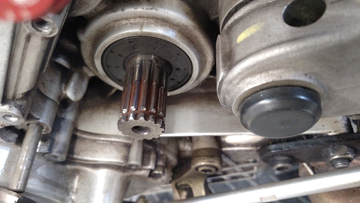
The donor sprocket below and the resulting spacer after machined
down:
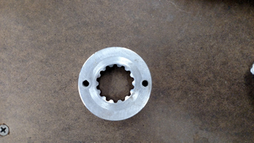
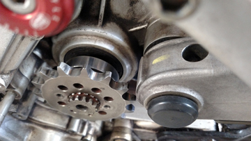
spacer in place:

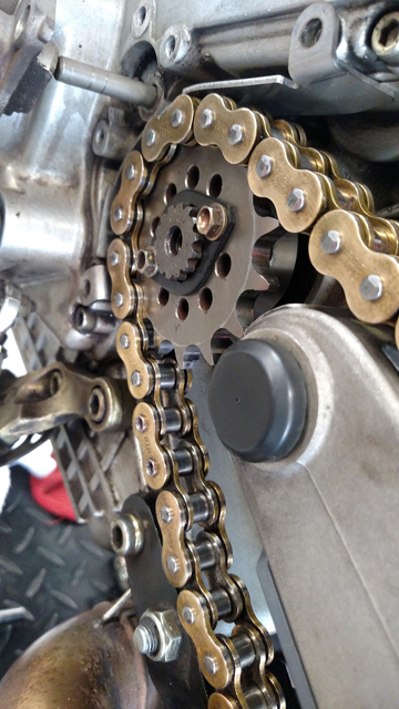
Installed and chain aligned!!! Note the difference in
swing arm reference marks with the chain CORRECTLY aligned!!!
[TOP]
|
9th Issue...
Radiator Pressure Cap part number incorrect in the Ducati Parts Catalogue.
Correct PN is:89310031A |
Listed in the ST4s Parts Catalogue as, PN
893.4.006.1A (CATALOGUE No: 915.1.130.1A , ISSUED: 05 - 01) which is NOT
the right Part Number for the cap required. Use Ducati Part Number
893.1.003.1A
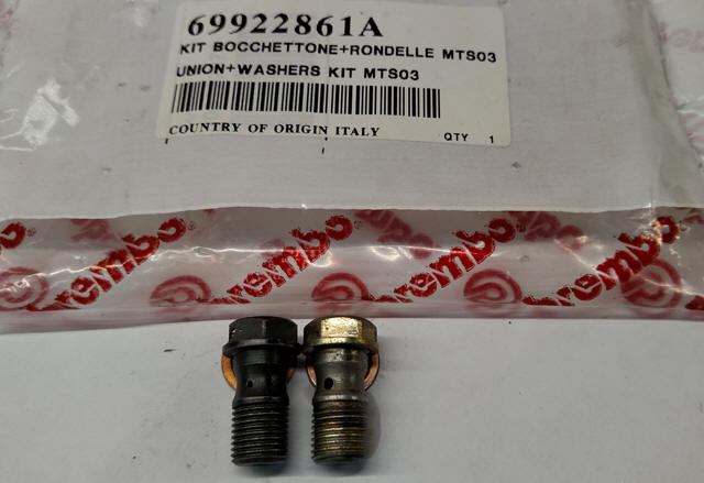
Common issue noted by many riders not just ST4s, not just Ducati
but, this is an issue noted on several Ducati forums (Ducati.ms (https://www.ducati.ms/forums/40-sport-touring/2151-brake-chatter.html)
and DucatiSportingClub.com
http://www.ducatisportingclub.com/showthread.php?t=25990) So I opted
to try the Ducati PN 69922861A - UNION+WASHERS KIT MTS03 Brembo banjo bolt.
[TOP]
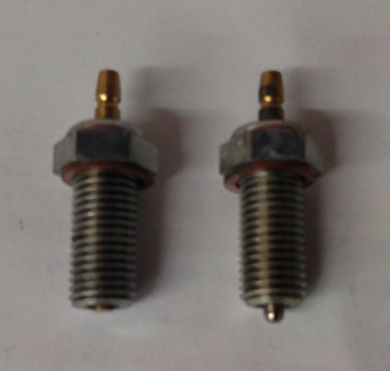
Another common issue noted by many Ducati riders (ST4s) included
is the intermittent and eventual failure of the neutral switch aka gear switch,
Ducati PN 539.1.021.1A. In the photo below you can see where the plunger
that makes contact in the gearbox to complete a path to ground when in neutral
is worn down.
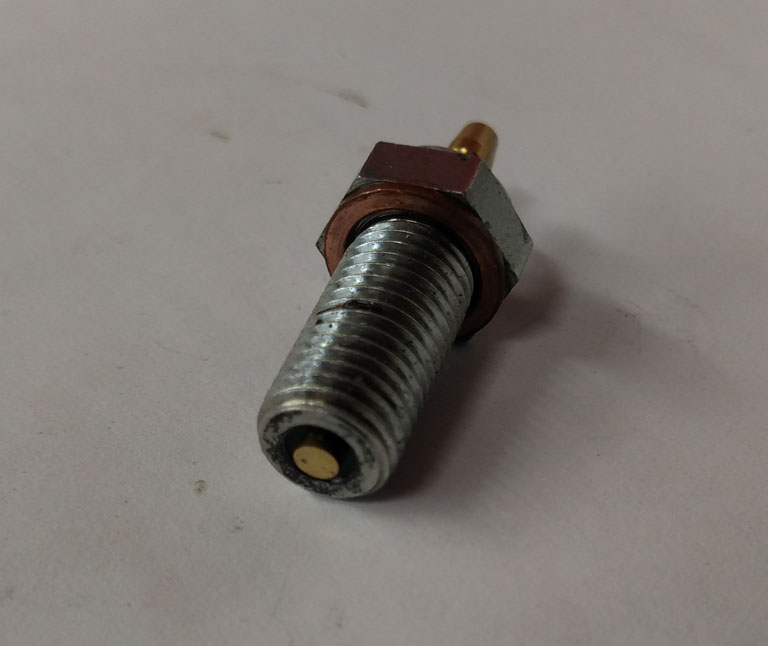
Old switch on left, new one on right.
Cut away view of the worn switch
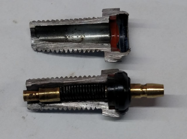
[TOP]
ST4s 2002 USA Parts Diagram:
click link for pdf |


