|
ECU Diagnostic
Software and Hardware Setup
& How to Make Changes To The MM ECU
ECU Diagnostic Software using OBD2 Type FIAT with JP Diag
or IAWDiag
** For JPDiag, a license is NOT required if your bike uses the IAW59M ECU (usually
applies to 2001-2004 Ducatis)
Required
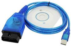
1. VAG-COM KKL 409.1 OBD2 USB Cable
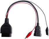
2. Fiat Adaptor = Fiat 3pin Alfa Lancia to 16 Pin Diagnostic Adaptor Cable OBD2
3. Cable Driver
4. Software - JP Diag
!!!! IMPORTANT !!!! --> INSTALL THE DRIVER BEFORE CONNECTING YOUR CABLES !!!
 |
 |
| VAG-COM KKL 409.1 OBD2 USB Cable |
Fiat Adaptor = Fiat 3pin Alfa Lancia to
16 Pin Diagnostic Adaptor Cable OBD2 |
Or, for a very reliable and better option purchase the LonElec kit, ships
from the UK, decent price and very highly rated! (no compensation for
endorsement, just my opinion shared by quite a few others)
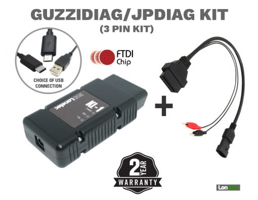 |
https://www.lonelec.com/product/guzzidiag-3pin-interface-cable-kit/ |
| GUZZIDIAG JPDIAG DUCATIDIAG KIT – INTERFACE + ADAPTOR
(KL & 3 Pin Set) |
|
For the USB cable, recommendations are to obtain FTDI driver based ones.
However, Winchiphead driver based ones will work after modification (described
below.) The two different type cables can be distinguished by plugging in
to a USB port. FTDI will not illuminate its LED, Winchiphead will
illuminate its LED. Also, the two fly lead Fiat Adaptor is best.
I do not recommend the single red lead version.
When you get your adaptor,
continuity test the fly lead. There have been instances of the wrong colors
being put on the crocodile clips. The red fly lead must terminate at pin 16 on
the OBDII female plug. The black fly lead must terminate at either pin 4, pin 5
or both. If wrong it can damage the ECU.
Cable Driver can be found here:
FTDI (http://www.ftdichip.com/Drivers/CDM/CDM20830_Setup.exe)
!!!! IMPORTANT !!!! --> INSTALL THE DRIVER BEFORE CONNECTING YOUR CABLES !!!
Once the drivers are installed and then the USB cable plugged into your PC,
identify the Com Port number for it in ‘Device Manager’ under Ports. A com port
number of 1 to 9 is recommended. Use advanced settings to change the com port
number if not.
The ECU Software Download is here:
JPDiag
Confirm the Com Port number for the lead using Device Manager. Enter the Com
Port number in the box on the Software.
Ducati motorcycles made between
2001 and 2004 are likely to have an IAW59M ECU. The correct setting for the
IAW59M ECU
is ‘Slow Init’. This ECU does not require a license for the diagnostic software
to fully function.
For bikes with the IAW5AM ECU use ‘Fast Init’ and a license is required to fully
function. Use the blue copy button in the software and then the request page on
the website.
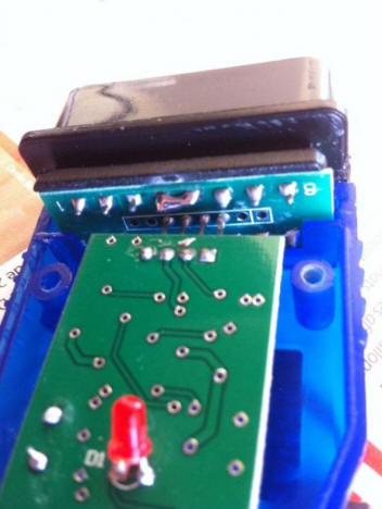
** If anyone does find that they have the Winchiphead lead then you need to
do a modification by making a solder bridge between pins 4 and 5. The picture
below shows how to.
As you launch JPDiag you will be presented with a screen displaying 3 picture
options of your cable setup. Choose which one corresponds with yours when the
time comes.
To be safe check your power lead pin out back to your ODB II cable before you
connect to anything at all by doing a resistance check with a multi-meter:
You'll see in the picture below the operating pins on the OBDII cable.
OBDII pin n. 5: Negative;
OBDII pin n. 7: K line (where the data travels to and from the controller);
OBDII pin n. 16: 12V +
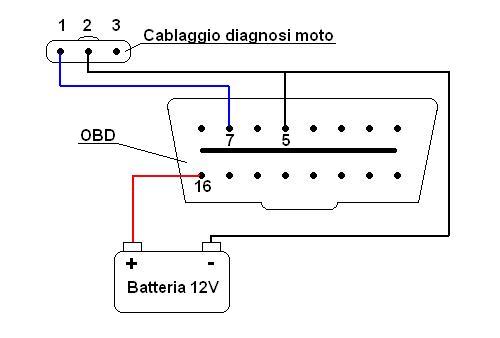
**Cablaggio diagnosi moto (Motorcycle diagnosis wiring) is the K Line
The pin you need to check is #16, it is positive power so set your
multi-meter to ohms and connect one probe to pin 16 and the other to the red
alligator clip. I simply inserted a largish sewing needle into the
corresponding female pin hole and connected the multi-meter probe to it to check
continuity. Check your negative while you're there too if you like, it's pin #5.
Pin #7 is the K line which you needn't concern yourself with.
That's your polarity check sorted. DO THIS BEFORE YOU CONNECT UP TO ANYTHING !!!
At this point you should have installed the correct driver and JPDiag.
Before launching JPDiag connect the cables -
1. Connect the OBD and Fiat cables together and plug them into the USB port of your
computer.
2. Look in Device Manager, under Ports to see which COM port the cables are using. You will need to know
the port number in case it needs to be corrected in JP Diag application. Make
sure to check this before connecting to the ECU. In Device Manager of your
computer, if you select the device listed under ports and right
click, go to properties and in the drivers tab you can check to make sure it's
operating with the right driver which should be FTDI if FTDI Based Chipset.
3. Connect red alligator to positive battery terminal and the black to a good
ground on your bike (negative).
4. At this stage a little blue LED will light on in the OBDII cable.
5. Launch JP Diag and select your cables.
6. Once the program interface opens you'll see a connect button alongside a
field into which you'll need to enter what COM port you're using.
7. Check the ini field setting - IAW59M use 'slow ini' IAW5AM use 'fast ini'
8. At this stage you can do another test on your cables. Set your multi meter to
20v and do as below:
Click Cable Test -
Connect the +ve and -ve fly leads to a 12v power supply e.g. your bike battery
but do not connect the diagnostic plug. Set your multimeter to 20v and connect
the +ve lead on the meter to the single outer pin in the Fiat Adaptor. It should
look like this [- | - -]. Connect the -ve lead from the meter to the middle pin
or the -ve terminal on the power supply.
Click on the connect button and the KLine 12v and KLine 0v tabs should become
selectable
Your meter will read in excess of 12v straight away. If you have the correct com
port you will be able to click on the KLine 0v and the voltage on your meter
will drop to 0.3v. Click on the KLine 12v and the meter will read over 12v.
If you don't get this behavior then the KLine is not working so check your
setting (probably Com Port)
9. Now if everything to this point is in order go ahead and connect your
Fiat
lead up to your ECU diagnostic lead (ST4s under the seat).
10. Click the connect button which is near the port # field and you will see on
the screen "connecting", I waited a little while then turned the ignition key on
and like magic on the left hand side in JPDiag you'll see the basic ECU data.
Copy it and post it in the request license form and you'll get a message back
from jpl which will include license file. This cle.lic file then needs to be
copied into the JPDiag directory .
**For IAW59M use 'slow init' and IAW5AM 'fast init'
Extra detailed information that you will not need but is informative to
understand ECU pin out and connectivity with the ECU.
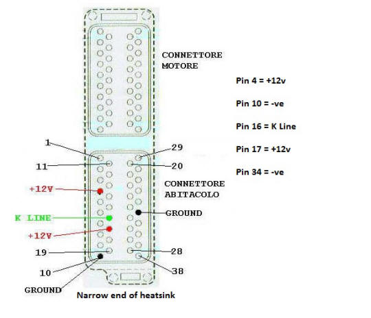 |
The pins you will connect to are:
Pin 4 = +12v
Pin 10 = -ve
Pin 16 = K Line
Pin 17 = +12v
Pin 34 = -ve
The side you connect to is where the heat sink screws are closest together |
Likely Issues:
1. Did you install JPDiag correctly. Did you click on the computer icon on
the second screen of the installation and then follow the prompts?
2. Have you set up the correct Com Port for the cable? Check in Device manager,
the lead will show up under com ports. If the com port number is over 10 then
change using advanced setting to a lower number.
3. With Win7 you need to navigate to the folder Program Files/JPDiag and locate
the file jpdiag28c.exe (the one with the icon of an Italian flag). Right click
on this file, select properties, select compatibility and then check XP Compat
Mode and Admin Rights. Then click apply.
4. Put the correct com port number in the box on the start screen of JPDiag. For
IAW5AM ECU's select Fast Init. For IAW59M ECU's select Slow Init. (IAW59M used
up to 2004)
5. With the leads connected to the bike. The +ve fly lead to + on battery, the -ve
fly lead to good earth on frame or engine. Click connect. You should see green
bar below that box and change to 'Disconnect'. Now turn ignition of bike on.
IAW DIAG Setting Trimmer Value
IAW5xM ECU has two types of memory:
Flash-Memory, where the bin-file (aka fuel map) is stored and EEPROM -
electrically erasable programmable read-only memory, where data like Serial
number of ECU, TPS-Valence-Trim-Value and is stored
When you flash your ECU, it does not change the EEPROM (you may see the eeprom-tool
from the guzzidiag-page) therefore, it is not necessary to complete a TPS Reset
if you reflash an existing ECU in your bike (No change to the TPS-Valence-Trim-Value
stored in EEPROM)
It is not harmful, but it is not necessary. Only changing the Hardware (ECU
or TPS) makes it necessary to do a TPS Reset, or a worn TPS.
For the CO-Trimmer Setting:
The 5AM ECU operates stock in Closed Loop Mode, and the CO is controlled by
Lambda sensors. The Value of the CO-Trimmer is set to zero from factory,
you can’t even change this value as long Lambda sensors are active.
If you reflash the ECU with a map "Lambda off" -- as described above the
Trimmer-Value remains at Zero.
The bike will run, even with no change to the CO-Trimmer. It will
run much better in the Low/mid-rpm range, if CO is set to around 4.0 - 4.5% as
measured with a gas-tester. If no gas-tester, set the CO Trimmer to a
value of around 24.
According to those with experience, CO level of 4.0 - 4.5% equates to a
trimmer value between 22 and 28.
How To "MAKE CHANGES TO THE
Magneti Marelli (MM) ELECTRONIC CONTROL UNIT (ECU)"
as
posted on Ducati.ms from Yorik:
WARNING – There is risk involved with
accessing the ECU. Reversing the power leads to the diagnostic cable can make
the ECU unusable. In other words, you will brick it and you will have to replace
it or find a work-around, if possible. I'm sure there are other ways, too. By
attempting to access your ECU, you accept all risks associated with doing so. No
one is making you do this and you do so willingly.
"This only covers ECUs made by Magneti Marelli since I will be limiting
discussion to the IAWDiag and TunerPro programs. I will not be getting into
technicalities. I’m a layman and that’s who this is written for.
If you have a different ECU, I suggest checking out M3C by JPDiag (for the M3C
ECU from Siemens) or Melcodiag (for Mitsubishi ECUs) also from the maker of
JPDiag to see if one of those will work for you.
But first, a few basics.
IAWDiag: A free/donation ware program (and associated programs) that allows
access to Magneti Marelli ECUs. IAWDiag is the generic version of GuzziDiag.
TunerPro: A program that allows a user to read and make changes to a bin file.
There is a paid version and a free version. The free version does what we need
it to do.
Bin file: A binary file that is found on the ECU. This is where the fuel map(s),
immobilizer flag, and other items that control the motorcycle can be found.
Xdf file: A file used by TunerPro that translates the bin into something that
can be understood by the user.
I’ll be covering two of the most popular items people ask about. One, loading a
new fuel map to the ECU and two, turning off the immobilizer. Other popular
things IAWDiag can do is reset the service indicator, adjust the CO trim, and
reset the TPS. (Just a note about resetting the TPS – you never want to
electronically reset the TPS if you have the non-linear type. That is done
manually.)
Before diving right in, you will need the following:
• IAWDiag (the main program is universal, but the associated programs that allow
you to read and write are ECU specific). GuzziDiag / IAWDiag"
• TunerPro (free version). TunerPro
and TunerPro RT - Professional Automobile Tuning Software
• Cables to connect the motorcycle diagnostic port to your computer. The most
trustworthy source is Lonelec. GUZZIDIAG
JPDIAG DUCATIDIAG KIT - INTERFACE + ADAPTOR (KL & 3 Pin Set) - Lonelec
Ok. Time to get started. The first thing you should do is just get familiar with
IAWDiag. There is a good tutorial online that covers GuzziDiag. And since
IAWDiag is the generic version of that software, they are very similar. The main
difference between the two is that GuzziDiag allows the user to select the model
of bike they have whereas IAWDiag makes you choose the ECU and TPS that the bike
has.
The tutorial can be found here: The
New Improved GuzziDiag Tutorial
(local pdf version here)
To determine the ECU your bike has, you can look it up in the service manual or
ask on the forum. To determine the TPS, the type will be embossed directly on it
if you have physical access or, again, you can ask.
Now that you have looked over the tutorial and have determined the ECU and TPS
combo you have, it’s time to connect to the ECU.
The safest way to do this is to first connect the two cables together. Then
connect the power leads to the battery. MAKE SURE THEY ARE NOT REVERSED. A
quality set of cables will have a power indicator light that will not come on if
the leads are reversed.
Now you can connect the other ends of the cables to the diagnostic port and
computer. Open IAWDiag and select your ECU/TPS combo in the Preferences
sub-menu. If you don’t see the combo you have, select your ECU and a TPS that is
of the same type as yours, i.e. linear or non-linear. You also have to have the
com port correct. Now you can select the Connect sub-menu item and follow the
prompts.
Hopefully, all went well and you’re now connected.
The Reader and Writer features can also be accessed through the IAWDiag program
menus or opened directly from their file location.
The first thing you should do if you are loading a new map or making an immo
setting change is to download a copy of the current file on the ECU. It’s good
practice to keep an unedited copy of the file in case you ever need to reload it
if the changes you made didn’t work or you don’t like the results of what you
did.
Before using the Read feature (which makes a copy of the bin file), it’s
advisable to remove the fuse for the headlight. The reading process isn’t very
quick and it’s best to minimize the drain on the battery. Now go ahead and Read
the ECU. Just follow the prompts.
If you are loading a new map, go ahead and use the Writer feature. This will
erase the ECU and upload the new bin file you have. This usually goes much
quicker than the read process. After uploading a new bin, you must perform a TPS
reset. Remember, do not use the TPS reset feature in IAWDiag if you have a
non-linear TPS. Resetting the TPS is outside the scope of this posting, but Brad
the Bike Boy has excellent information about it at his website: BikeBoy.org as
does Desmo Times’ maintenance guides by LT Snyder.
If you are disabling the immobilizer, you will be using TunerPro. Open the
program and then open the bin file you downloaded from your bike. You will also
have to select a proper xdf file to translate the bin so you can make changes.
Because xdf files are made by the DIY community, not everything you may need
exists. We are at the mercy of the people out there that have the knowledge and
ability to decipher bin files properly.
Most xdf files are named well enough to get an understanding of what bins they
are designed for, but sometimes they also work on others. Finding an xdf that
works can sometimes be hit-and-miss. And to add occasional grief, not all xdf
files have the immo flag so that you can toggle the setting. The simplest way I
have found to check if an xdf looks good is to load it up with the bin in
TunerPro and open the main fuel map. If it doesn’t look right, and it’s fairly
obvious when it isn’t, then it’s time to try another. The RPM and TPS scales
will be off and the map will look wrong. Do not attempt to use an xdf that looks
wrong.
If you find a working bin/xdf combo with the immo flag, all you have to do is
uncheck the checkbox and save the bin. That’s all there is to it. Be sure to
save it as a different file than the original. Upload the modified file using
Writer and that’s it. |