Fork Disassembly and Overhaul
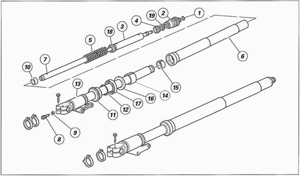
Figure 3 2002-2003 Ducati ST4s Workshop Manual Showa
Fork Diagram
These steps that follow are
for a complete disassembly of the fork necessary for complete inspection
and renewal of bushings and seals. A photo of completed fork
disassembly is below,
Figure 12
with numbering of the parts IAW 2002 Ducati ST4s WSM (numbering changes
in other years WSMs). Ensure that the area you are working in is clean
and free from sand, hairs, metal chips, etc.
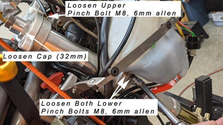
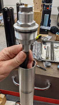
1. With
fork cap still installed, support and secure the fork horizontally,
careful not to mar the stanchions or sliders and using a 19mm socket and
impact gun, loosen but do not remove the compression adjuster in the
bottom of the fork. This step is necessary to loosen the compression
adjuster (it is like a very fancy bolt with a copper washer). Once
loosened, simply snug it back up by hand so that fluid does not
excessively leak out of it when you return it to vertical. A little
weeping of fluid is fine, just catch it with a rag. Figure
4 Showa Fork Compression Adjuster Loosen / Removal
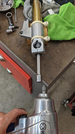
Figure 4 Showa Fork Compression Adjuster Loosen /
Removal
2. Hold
fork vertically and using 32mm wrench or socket, loosen the fork cap so
that the last thread disengages completely, and the upper stanchion can
slide down and expose the spring collar (internal metal tube) with the
two holes. Figure 5
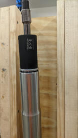
Figure 5 Showa Fork Cap Removal
3. Use
the fork spring compression tool inserted into the two holes on the
spacer to move the spring joint (spacer tube) down and expose the hex
nut that fastens the upper plug to the damping rod. Once the hex nut is
exposed, place the retention plate hold down tool between the hex nut
and the top of the tube. (This may be a two person job and requires
some physical exertion. I built a fork holder with a jack to hold the
special tool and fork in place and allow it to be done solo.) Figure
6
Note: oil can spill out from
the top of the opened fork tube.
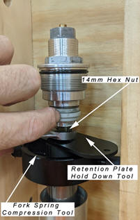
Figure 6 Showa Fork
Disassembly Tools
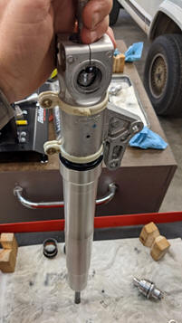
4. Remove
the upper fork cap plug by holding the hex nut on the rebound adjuster
fitted on cartridge rod (#7 in Ducati WSM
Figure 3)
in place with a hex wrench (14mm) aka spanner and unscrew the complete
upper plug with 32mm socket or by hand. (Be careful, there are small
plastic and delicate metal rods in the upper plug that can be easily
damaged or lost.
Figure 6
5. Remove
the spring collar with the plastic spacer and washer and then the
spring, and spring spacer tube.
6. The
oil can then be poured out of the fork body. Gently pump the fork leg
upside down while over a pan to catch oil. Oil is captured internally
and pumping it will ensure that most of the oil has been removed. Oil
will squirt out of the small orifice at the top of the damping rod.
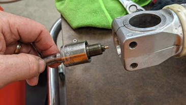
Figure 7
Showa Fork Compression Adjuster - Removal
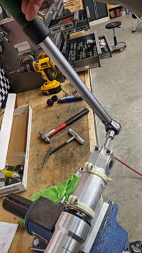
7. Once
again, support and secure the fork horizontally, and withdraw the
compression adjuster with a 19mm socket from the bottom of the fork.
You may want to use the impact gun to spin the adjuster free of the
damper cartridge, or otherwise keep the damper cartridge from also
turning while attempting to withdraw the compression adjuster. It has
very fine threads and it as well as the damper cartridge can be easily
damaged so take care in the process. With the adjuster removed the
cartridge / damping rod and the lower centering bushing can be
withdrawn. Figure 3,
parts #7 and #10
Caution: Do not open the
damper cartridge.
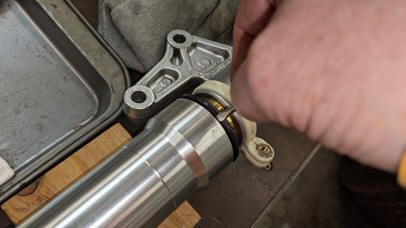
Figure 8 Showa Dust Wiper
- Removal
Figure 9 Showa
Fork Seal Circlip - Removal
8. With
the fork supported horizontally (use soft cloth or rags etc. to prevent
any marring or scratches) on work surface, using a small screw driver,
loosen and remove the dust wiper out of the stanchion. Slide it up the
stanchion tube for the time being. Figure
8
9. Remove
the circlip retaining the fork seal next. With a small screwdriver,
carefully work the end of the wire clip out of its recess and then
remove by hand. Figure 9
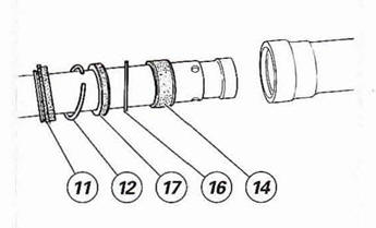
Figure 10 2002 Ducati ST4s WSM Showa Fork Pilot Bushing and Seals
10.
With one hand on the slider
(the fat silver outer tube - 53mm) and the other hand on the stanchion
(gold not as fat inner tube 43mm that slips inside the slider) and pull
apart firmly tapping repeatedly to remove the slider from the stanchion
tube. Figure 11.
Repeated tapping to free the pilot / guide bushing (#14 in the Ducati
WSM Figure
10.)
that is forced into the slider.
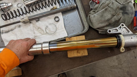
Figure 11 Separate
Fork top and bottom
11. Once
separated, place the fork halves on a suitable work surface, protecting
them with soft rags etc., and supported horizontally then using a screw
driver gently pry the bushing open (#15 in the Ducati WSM Figure
3)
and remove from the stanchion tube. The pilot or guide bushing (#14),
seal (#17), retainer (#16), and dust wiper (#11) can be withdrawn as
desired.
Figure 10.
Photo of complete
Showa Fork disassembly:
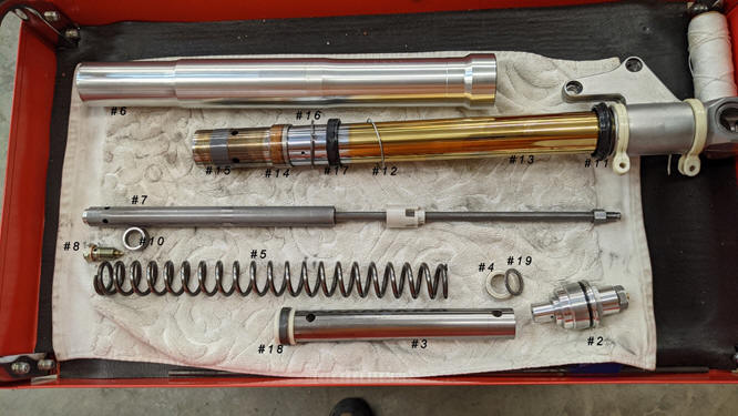
Figure 12 2002 Ducati ST4s Showa Fork Disassembled and Labeled IAW 2002
Ducati ST4s WSM
Inspection:
1.
Measure the spring length,
with the spring on a flat surface, measure its free length, it should be
370mm in length. (The Ducati WSM has a typo for ST4s; it shows 270mm
spring length which is incorrect!)
2.
Examine the outer surface of
the two stanchions and the inner surfaces of the two sliders. They
should be free of scoring, notches, or signs of forcing.
3.
Check that each stanchion
slides smoothly inside the sliders and that there is not excessive play.
4.
Ensure that the stanchions
are perfectly straight. Max. deviation allowed: 0. 10 mm
5.
Inspection of the bushings
may occur here as well, but if you are this far along, you are probably
replacing them.
6.
Ensure that the bushing
retainer (Part #16 in the Ducati WSM Figure
13
below) is not bent. If it is bent, change the retainer…it is like a
large washer…the cross section does not look like fig 13 from the Ducati
WSM below, but if it is bent – replace it.
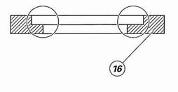
Figure 13 Inspect the indicated area of the bush retainer
Assembly:
Caution: Lubricate the sliding
edges with fork oil or seal grease before reassembling the oil seal
(#17)
1. Wrap
fork stanchion top with some adhesive tape or use plastic covering to
protect the seal as it slips over the edge of the stanchion and bushing
channel. (Figure
14)
I used a bit of plastic from a smooth plastic water bottle, cut and then
lubed up with fork oil. Slide the seals on the plastic past the channel
that the bushings sets in, so as to avoid the sharp metal edges nicking
the seals.
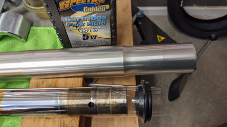
Figure 14
Plastic covering to protect the seal
2. Fit
the following parts into the stanchion according to the given order:
a.
Dust wiper (seal) (#11)
b.
Circlip (#12)
c.
Oil seal (#17)
Caution: Fit the oil seal with
the marked surface facing the dust seal.
3. Fit
the following parts into the stanchion according to the given order:
a.
Retainer (#16)
b.
Pilot bushing (#14)
c.
Stanchion bushing (#15)
Caution: Remove any burrs and
make sure not to damage the bushing outer coating.
4. To
make the next operation easier, tape dust wiper seal and circlip
together out of the way.
Note: Lubricate the bush
sliding surfaces with fork oil before reassembling.
5.
Push the pilot bushing (#14)
and the retainer (#16) into the slider with the seal driver 43mm
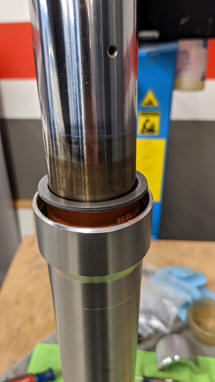
Figure 15 Pilot bushing
and retainer
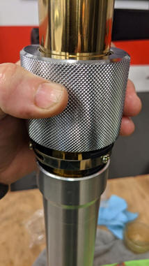
Figure 16 43mm seal driver
6.
Push the oil seal (#17) into
the slider using the seal driver 43mm
7.
Fit the circlip (#12) and
the dust wiper seal (#11)
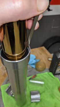
Figure 17 Fit circlip
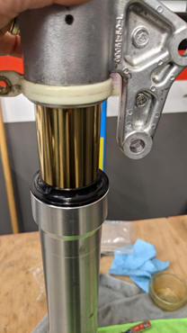
Figure 18 Fit the dust wiper
seal
Caution: Ensure that the
slider slides smoothly along the stanchion tube. Hold both stanchions
and sliders in your hands not to damage oil seals and pilot bushing
8.
Support and secure the fork
9.
Fit the lower
centering bush (#10) into the damper cartridge end (#7) and then fit
them into the slider (outer tube) [I like the
fork bleeder tool from Traxxion Dynamics and thread it to the damper rod
threaded end to help hold the damper rod in place when fitting the
compression adjuster]
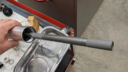
Figure 19
Traxxion Dynamics fork bleeder tool
10.
Fit the copper washer
seal (#9) and the compression adjuster (#8). Tighten to 30-40 Nm.
[To torque the compression adjuster to the base
of the damper cartridge, you may want to temporarily attach the upper
plug (#2) to the damper cartridge hand tight and then fit it to the
upper stanchion, hand tight in stanchion. Once the compression adjuster
is torqued, remove the upper plug from the stanchion and damper
cartridge and continue with step 11.]
11.
Fill each fork leg with half
the amount of the specified oil (half of the 492cc)
12.
Fill the damper rod from the
top hole until oil comes out from the side vent hole
13.
Pump the rod and the
slider up and down at least 10 times (completing a stroke of a least 150
mm) so that the oil fills the fork leg and cartridge completely…be
careful to not spray the fork oil out of the fork
[Again, I use the Traxxion Dynamics fork bleeder tool to
keep the fork oil from going all over the place and making the bleeding
much easier]
Note: Oil will squirt out of
the hole in the top of the damping rod as rod is pulled up. It is
possible to insert the spring and spacer and then attach the upper plug
(#2) to the damping rod, then compressing the spring joint with the
pusher tool, keeping the oil from spraying out of the fork.
14.
Move the damper rod and the
slider to the end of their stroke.
15.
Pour the remaining oil into
the stanchion tube and measure the oil level (Fork Oil Level: 132mm
spring out, spacer out; 110mm spring in, spacer out; or 94mm spring and
spacer in)
Caution: The fork leg must be
in a vertical position when measuring the oil level. Ensure that both
fork legs have the same oil level.
16.
Recommended oil and
capacity:
a.
Shell Advance Fork 7.5w,
DONAX TA or Spectro 5W CRT fork
b.
Standard capacity: 492±2.5
cu.cm
c.
Standard oil level: (132mm
spring out, 110mm spring in, 94mm spring and spacer in)
d.
The amount of oil in a fork
affects the performance of the fork in the compression stroke
e.
High oil level will increase
the compression load; a low oil level will decrease the compression load
17.
Wipe any oil from the spring
and the spring collar before reassembling
18.
Fit the following parts:
f.
Spring (#5), with the
tapered section facing the collar (#3)
g.
Spring collar (#3) with the
ring (#18)
h.
Slider (#4)
i.
Upper washer (#8)
19.
Fit the compression tool
(used for disassembly) into the side hole in the spring spacer tube
collar (#3)
20.
Push the tool down and slide
the holding plate (C) under the lock nut of cartridge (#7)
21.
Screw the upper plug (#2)
onto the rebound adjuster on cartridge (#7)
22.
Using a hex wrench (spanner)
hold the rebound adjuster in place and tighten the upper plug to 30-40
Nm
23.
Push the compression tool
(A) downwards and slide out the holding plate (C)
Warning: The adjuster (D) of the
top cap (#2) must be fully slackened.
24.
Screw the upper plug (#2)
onto the slider and tighten to 30-40 Nm.
25.
Fit the wire snap ring
circlip (#1)
Reinstall forks:
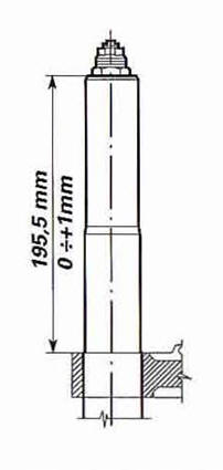
Figure 20 Fork
Install Height - Location
1.
Insert forks into triple
tree through lower clamp and into position in upper clamp, locate the
fork in the clamps as depicted in the diagram above,
Figure 20.
2.
Tighten pinch bolts per the
work shop manual torque values and sequence.
a.
Steering Head Bolt 23 Nm
(Grease B - Shell Gadus S2 V220 2)
b.
Bottom Yoke Bolt 20 Nm
(Grease B - Shell Gadus S2 V220 2) 1-2-1 Sequence
3.
With the pinch bolts
tightened, tighten the fork cap to 30 Nm – 40 Nm.
4.
Fasten Handle Bars to the
Steering Head (M8x1.25) torque 24Nm.
Reinstall the front wheel:
Ensure that the axle will
slide into both RH and LH forks with minimum force. If you must force
the axle through to the LH fork, the fork legs are not at the same
level. Readjust the fork legs with respect to each other.
Make sure that the speedo
drive ring is in the wheel before putting the wheel on the bike. The
speedo ring has two tangs that line up with two grooves in the speedo
drive unit.
Now place the wheel between
the forks and insert the axle from the RH side and also place the speedo
drive onto the axle. Rotate the axle to line up the holes in it with the
compression adjusters in each fork.
Make sure you line up the
speedo unit properly so that the tab on the lower LH fender mount fits
into the outer groove of the speedo.
Once the axle is in, put on
the axle nut hand tight. Put the calipers back on at this point.
Tighten the axle nut with a
wrench, but not fully and ensure that the axle is seated against the RH
wheel’s inner bearing race. Tighten the two RH axle clamp bolts just
enough to stop the axle from turning. Fully tighten the axle nut. Fully
tighten the LH axle clamp bolts.
Loosen the two RH axle clamp
bolts that you previously tightened.
Remove the bike off the front
stand. Pump the front brake lever a few times to seat the disc pads.
Next, bounce the suspension up and down till you are sure that the RH
fork has had a chance to stabilize into position.
Tighten the two RH bottom fork
axle clamp bolts